
Link to this section Overview
This project is a new type of MIDI controller which uses a LiDAR sensor to detect the positions of the user’s hands within two arbitrary zones, then maps this input to four separate MIDI streams. Each stream can send either note values to control pitch or Continuous Controller (CC) messages to control other parameters in a DAW.
This controller uses a single sensor placed in the middle of a playing surface (desk, table, etc). The performer sits or stands such that the sensor is directly in front of their body. On either side of the sensor, zones are marked out in software. These zones can be chosen to align with physical references, such as a printed grid. The performer positions their hands within these zones in the air above the playing surface. Then, the horizontal and vertical position of each hand is used to generate MIDI messages, which control some sound source.
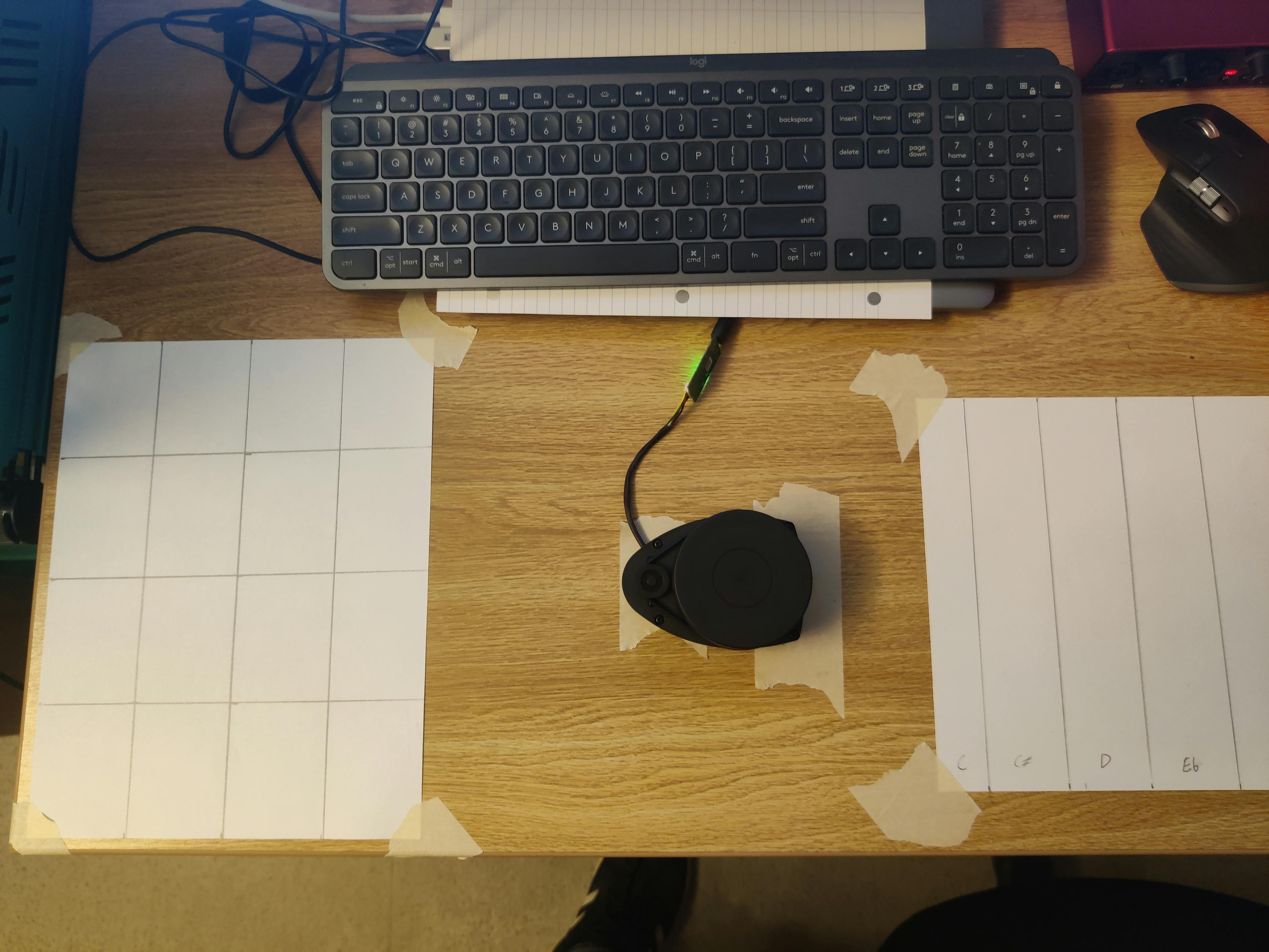
The sensor located on my desk, with two reference sheets corresponding to two zones.
Link to this section Motivation
My primary inspiration for this project was the theremin. I had the opportunity to play one when I was young, and I was amazed by how intuitive and inviting the instrument felt. I was quickly able to get a sense for how the pitch and volume were controlled, but I still had the sense that there were so many possibilities for the device despite the simple controls. I was also struck by how inviting the device felt. Generally, when I see an unfamiliar instrument, my first reaction is to hold my hand tentatively over it and ask, “Can I play this?” With the theremin, simply being in the same vicinity affects the sound, and when I curiously held my hand near it, I found I was already playing.
Although some highly skilled musicians such as Clara Rockmore developed techniques for the theremin that increased its versatility, the instrument is often used simply for “spooky sound effects” instead of pitched music. The ondes Martenot, a later electronic instrument using a continuous wire, had a non-functional image of a piano keyboard which provided a reference point. This instrument was just as continuous as a theremin, but the reference keyboard made it more widely used in pitched music. It also allowed for multiple configurations of the resonance diffuser, giving the instrument a wider range of timbre.
A more modern inspiration was Quadrant, a MIDI controller developed by Chris Chronopoulos from 2018 through 2021. This controller uses upward-facing time-of-flight sensors to determine the pose of the player’s hand. Notably, it features a variety of different control modes: using four sensors, it can detect the position, velocity, orientation, and angular velocity of the performer’s hand. It also features special modes which can detect sweeps of the hand across the instrument, or plucking motions made above each of the four sensors. Of course, being a MIDI controller, it can be used to control an incredible variety of digital sound sources.
I was also inspired by the laser harp, another modern MIDI controller played without contact. Again, I appreciated how intuitive the device seemed: by leveraging the existing understanding that people have of traditional harps, the laser harp makes its controls obvious.
With this project, I wanted to create a controller that operated in free space, just like the theremin. I wanted to give a reference to allow for more precise pitch control, like the keyboard provided by the ondes Martenot. I wanted to support various control modes, in a manner similar to Quadrant, and I wanted the device to leverage existing intuitions people have about theremins in the same way the laser harp leverages existing intuitions about harps. Above all, I wanted this controller to be as intuitive and inviting as the theremin felt to me when I was younger.
Link to this section Technical Description
Link to this section LiDAR Sensor
For this project, I am using a LiDAR sensor, specifically the Slamtec RPLIDAR A1. This sensor is used to detect the position of the user’s hands in free space. It features an infrared laser diode and a receiver, mounted on a spinning platform.
This sensor is a type of Time-of-Flight (ToF) sensor. It functions by sending out a pulse of infrared laser light and measuring the time taken for the light to bounce off of an object and return to the receiver. Stationary ToF sensors, like those used on Quadrant, produce a stream of distance values:
[...]0.505452 m0.501343 m0.499432 m0.476832 m[...]
Each of these values represents the distance from the sensor to the nearest object it sees at a specific instant in time. The range of these sensors varies: the sensors used on Quadrant had a range of about 1 meter, while this sensor can measure up to 12 meters. As there are no external factors that drastically affect the speed of light, these readings are generally quite accurate.
By mounting the ToF sensor onto a rotating platform, it is possible to measure at many different angles and construct a 2D map of the sensor’s surroundings. For this reason, these sensors are often used in robotics, to allow a mobile robot to map its environment, determine its position, and navigate. While LiDAR sensors are used in some autonomous driving applications, they are most commonly used in some high-end robot vacuum cleaners to map and clean a given area. For this MIDI controller, application however, the sensor is kept stationary.
By combining the distance measurements from the laser diode with the angle of the rotating platform at the time of measurement, the sensor constructs a stream of angle/distance pairs.
[...]30.12° 0.505452 m31.10° 0.501343 m32.07° 0.499432 m32.98° 0.476832 m[...]
The sensor used for this project produces a stream of about 1,500 such pairs every second and sends this data to the computer over a serial port.
Link to this section Sensor Control/Processing Program
The sensor data is then passed to the first of two computer programs I wrote for this project. This first program is responsible for processing the sensor data and determining the position of each hand within each zone. If the sensor is rotating quickly enough, we can consider every measurement taken in one rotation as a single snapshot in time. Then, for each angle/distance pair, we can plot a point on a graph at the given angle and distance from the origin. In other words, we convert the pairs of coordinates to pairs of coordinates and display the result.
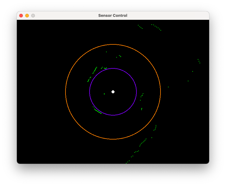
Pictured above is the graph that is generated from this process. In this image, the green dots represent points found by the laser, and the purple and orange rings mark distances of 50 and 100 centimeters away from the sensor respectively. This scan was performed in my dorm room. This complete plot of the environment includes the performer’s body, the walls of the room, and any other objects in the environment at the sensor’s height. Next, it is necessary to filter out anything from the environment which should not affect the output, i.e., everything except the hands of the performer. I decided to accomplish this by processing two separate zones in the pot, such that the performer could move each of their hands within its respective zone in two dimensions. This results in four separate axes of control. The use of two separate zones was chosen to maximize the number of axes available to the user, and to eliminate the possibility of one hand obscuring the other.
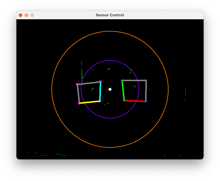
The user can select these two zones by clicking each of the eight corners on the graph. In the chart above, my left hand is visible in the zone on the left side and my right hand is visible in the zone on the right side. The sensor, represented by the white dot in the center, is located in the middle of the playing surface, between the zones and directly in front of my body. The software will calculate the position of each point in the scene along each of the four axes. To do this, it constructs a projective transformation matrix, which is a technique from linear algebra. The following procedure was adapted from this StackExchange answer by Dr. Martin von Gagern.
The software knows the coordinates of each corner in space, and it knows the position of each corner relative to each axis (the point where the two axes meet is , the opposite corner is , etc). Using this, it will construct a transformation matrix that can map any point in space to its position relative to each axis. Intuitively, the most obvious approach would be to construct a matrix to perform this mapping, since we are working with pairs of coordinates. However, since we have four separate known mappings, the matrix would have too many conditions to meet. The system would be overdetermined and thus impossible to solve.
We can add “wiggle room” to the system by using a matrix instead. However, this requires representing our coordinates using triples instead of pairs. In other words, this requires some way of representing coordinates in the form instead of . One such approach uses homogenous coordinates. Mapping Cartesian coordinates to homogenous coordinates requires adding a 1 in the third position (such that becomes ), and mapping homogenous coordinates back into Cartesian coordinates requires dividing the first and second coordinates by the third coordinate (such that becomes ). Notably, this system creates a set of points with homogenous coordinates of the form which cannot be mapped to Cartesian coordinates due to the division by zero. Conceptually, these points represent scenarios like the following:

The above point is around on Axis 0, but it has no meaningful coordinate on Axis 1. As the positions of the performer’s hands should be inside the quadrilateral zone, scenarios like the above should never arise in this application. For each zone, the software will map the four corner points to their homogenous representation, then compute the transformation matrix. Then, it will sort the points based on whether the lie inside the zone. It determines if each point is inside the zone by checking if its position on either axis is less than zero or greater than one; although more optimized methods of testing if a point is inside a quadrilateral certainly exist, I found the matrix multiplication to be approach reasonably performant, so I decided against introducing additional complexity. Finally, to create a single value for each axis, the software will average the axis positions of each point located inside the zone. This step produces a stream of four numbers, representing the position of both hands along both axes in their respective zones:
[...]0.43 0.53 0.21 0.540.41 0.57 0.19 0.500.42 0.61 0.19 0.52[...]
This stream of values is then passed to the second program.
Link to this section MIDI Mapping Program
The second program handles mapping each axis to a stream of MIDI data. Each of the four axes are handled separately. The program provides a control panel which allows configuring the parameters of the MIDI stream.
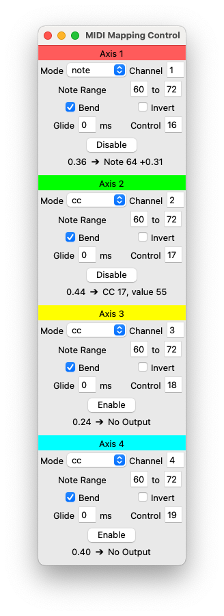
Each axis can be mapped to either note messages or Continuous Controller (CC) messages. For note messages, the range of notes is configurable. Additionally, pitch bend messages can be sent to smoothly interpolate between notes. As currently implemented, transitioning from one note to another smoothly requires that the sound source envelope not have attack/decay or this attack will be audible when moving between notes. For CC messages, the control number can be chosen. Both modes support setting the channel number, which is useful for having different axes control different synth voices. A setting to invert the signal is also provided.
Link to this section Surface Configurations
Since the scanning occurs about 2 inches above the tabletop, the user does not need to touch any surface to use the controller. This allows any variety of surfaces to be placed underneath the setup. The simplest configuration has no reference material whatsoever. However, I found that this made it difficult to use, as I would frequently move my hand into or out of the zone without knowing, unexpectedly playing or stopping a tone.
I also tried placing a piece of paper in each zone and calibrating the corners of the zone to the corners of the page. This solved the aforementioned issue. This configuration worked well for controlling a filter or some other aspect of the sound timbre, but I found that an 8.5x11” zone was too small to precisely control pitch. I also found that, without any sort of reference, it was almost impossible for me to precisely reach a specific note. At this time, I tried decreasing the range of the controller from 2 octaves to 1 octave in an attempt to improve precision, without much success. I also tried disabling the pitch bend messages to see if snapping the hand position to the nearest note would help, but I did not notice any improvement in usability.
Next, I tried an asymmetrical layout, with a portrait-oriented paper on the left and two landscape-oriented pages arranged lengthwise on the right. The left page showed a 4x4 grid, and the right pages had vertical lines denoting the boundaries between notes. I found that this made me much more able to hit a specific note within the octave range, even if I re-enabled pitch bends. That said, I did not play along to any other instruments, so I might have overestimated my ability to precisely reach a particular pitch.
I found it difficult not to hit intermediate notes. While moving my hand, even quickly, if a scan saw my hand in the middle of the move, it would play the intermediate note for about 150ms, which sounded jarring at times. To compensate, I played by lifting my hand up away from the zone before moving it side-to-side between notes. This created an additional issue: due to the shape of my hand, moving it up and down could alter the detected position along the forward-and-back axis. I tried playing using a credit card instead of my hand but found it just as easy to ensure my hand was not tilted forward or back when moving it up or down.
Link to this section Mapping Configurations
The first mapping I tried used the controller to control a wavetable synthesizer in Ableton Live. It used the right hand horizontal axis to control pitch and the right hand vertical axis to control the position on the wavetable. The left hand controlled a low-pass filter, with the horizontal axis controlling the frequency cutoff and the vertical axis controlling the resonance parameter. I found wavetable synthesis to be a natural fit for this controller, since having a single parameter as the primary control of the sound’s timbre could give one hand control over both pitch and timbre, freeing up the other hand for controlling an effect or a second sound source.
My attempt at controlling two synthesizer voices with this project used one hand for each voice, making use of my software’s ability to send MIDI note messages on different channels corresponding to the input axis. I again used the horizontal axis for pitch. One patch was a sawtooth wave bass, with the vertical axis controlling a low-pass filter, and the other patch was a square wave in a higher octave, with the vertical axis controlling a delay effect. I found controlling two separate voices to be overwhelming. This was mostly because I needed to visually look at each hand to position it properly, which was difficult as they were on opposite sides of the playing area. I also found the delay effect control to have little utility outside of “spooky sound effects.” I did enjoy “tuning” the two voices to an interval by ear (since I was not playing with a note reference at the time) and controlling an almost-exact-interval with my hands to slightly tune or detune it produced some interesting sounds, but this was made difficult by the latency issues (discussed in a later section).
Returning to the wavetable and low-pass filter mapping, I tried an alternate playing style by placing a small object in the filter zone to hold those axes at a specific point. This allowed me to focus more on playing melodies with my right hand and less on holding my left in a specific stable position. However, it also removed the “free space” aspect of the controller for that zone, and it took away from the direct coupling of hand-to-sound, reintroducing that hesitance before manipulating a control. Ultimately, this playing style is a tradeoff, diverging from my original vision in pursuit of usability, and I believe having it as an option is a net benefit.
Finally, I tried using the controller in conjunction with a traditional MIDI keyboard. I deactivated the right side zone, placed the keyboard in its place, and kept my left hand in the left side zone. I found that this combination worked surprisingly well: the traditional keyboard allowed me to play notes accurately and with minimal latency, while my left hand was free to alter the timbre of the sound. I found the LiDAR controller felt much more expressive than a simple mod wheel; even though it had similar precision, having a large physical representation of a parameter gave me a better sense of the possibilities it provided, and coupling my hand directly to its output made experimentation feel more direct and natural. While this configuration also does not follow my initial vision for a single, configurable, all-purpose MIDI controller, it succeeded in allowing for intuitive and inviting free-space control of timbre while falling back on a familiar interface for pitch.
Across each of these configurations, I found that mapping two related parameters to a single hand fundamentally changed how I conceptualized the controls. I tried a few mappings of this sort, such as controlling the frequency and resonance of a filter, the time and feedback of a delay module, the amount and wet/dry mix of an overdrive effect, and the rate and feedback of a phaser. In each of these cases, I found I had a much better sense of the timbre possibilities offered by these controls. With a traditional controller, with single knobs mapped to single controls, I would typically move just one knob at a time and miss vast swaths of potential sounds. Having two parameters mapped to 2D space encourages moving diagonally or in a circle to modify both parameters at once. Even though traditional CC controllers allow mapping the same knob to several controls, it is not the typical use case.
One of my favorite moments was finding a particular spot in the 2D zone that caused the filter to resonate particularly strongly or the phaser to fit the melody I was playing perfectly. Exploring these pockets gave me the sense that I was exploring something inherently two-dimensional, instead of just manipulating two parameters at once.
Link to this section Results
Link to this section Scan Latency
The issue of scan latency proved difficult to overcome. The LiDAR sensor that I use spins at about 380 RPM when connected to 5V power, leading to an effective latency of around 150 milliseconds between scans. This had a few adverse effects on the usability of the controller.
The first issue with the scan latency was the creation of a 150ms “rhythm” in the audio output. The output would jump sharply to a new pitch whenever scan data was received, so if the user were to attempt a gradual slide between notes, the result would sound much choppier than intended. A potential remedy is to interpolate smoothly between scans, ramping to each value just as the measurement following it is received, but doing this would double the effective latency of the controller. This behavior could also perhaps be used for effect if a piece were specifically written around it, but the sensor used in this project does not provide an easy way to precisely control the speed of the scan motor, so synchronizing it to a track would be difficult. Given the scope of the project, I decided against trying to implement precise motor speed control, although this could be a direction for further experimentation.
The latency also proved to be a barrier for precise control. I had assumed that 150ms, while by no means ideal, would be passable for syncing with the beat of slower music, but I overlooked the impact of latency on other aspects of performance. With a continuous instrument (such as a theremin, or playing a guitar with a slide), the performer will adjust in real-time using their ear until they are playing the correct pitch. With the LiDAR controller, the presence of latency disrupts this real-time adjustment, making it extremely difficult to play in tune. Removing the pitch bend messages and snapping each position to the nearest semitone helped, but it was still difficult to precisely position one’s hand in a specific 1/12 of the zone without any markings for guidance. Ultimately, a visual reference was required to accurately play pitches, and even then, the controller was difficult to use.
Link to this section Future Directions
One direction I did not explore was integrating graphic scores into the project. While I tried a configuration with a general note reference on the surface, it would also be possible to use a reference designed for a specific piece of music. Such a reference would be, in a sense, musical notation for the piece. A potential difficulty with this is the lack of a “time” axis to draw on, which could make duration or progression difficult to express in this notation.
Another potential direction is to use interpolation to reduce the jarring steps between scans. I intended to implement this, but the way in which I structured my software did not lend itself well to this approach, and a major restructuring would be needed. I am curious as to how adding glide between scans would affect the perceived latency of the controller, and how much it would improve the discontinuity between scans. Notably, different amounts of glide could be explored. For example, interpolating for the full 150ms would yield the smoothest output but the greatest latency, but perhaps a glide of 20ms could mitigate most of the jarring clicks/jumps in the audio with a minimal impact on latency. Additionally, different interpolation functions could be explored.
More direct control over the sensor itself could be explored. The specific model of LiDAR sensor I used lacks an interface to control the motor speed or scan rate. A sensor with more features could allow tweaking these parameters, potentially leading to reduced latency and/or increased precision, especially since LiDAR sensors are typically calibrated to scan an entire room instead of a tabletop surface. The scan rate could even be tuned to match the tempo of the music being played, resulting in a much more predictable playing experience and eliminating the issue of sudden off-beat jumps in output.
Finally, gathering the perspectives of others would be an important next step. Due to the timing of this project ending over spring break, I did not have much opportunity to share this project with others. Of course, when I tested the controller, I brought along my past intuitions and experiences. Other users would be drawing on different prior intuition when using the controller, and understanding its usability from more perspectives could inform how it could be made more intuitive and more inviting.