This hack rewires an Adafruit MagTag to function as a handheld Meshtastic node. The device runs BaseUI on the E-Ink panel and is controlled via the four front buttons. The Meshtastic firmware port supports ambient lighting, battery voltage monitoring, and I2C sensors. Adapting a stock MagTag can be done relatively easily with a replacement 3D-printed rear cover, a Seeed Studio Wio-SX1262 module, and some bodge wires.
Link to this section Motivation
A few months ago, my girlfriend Mia bought a MagTag from Adafruit. It's a small board with a microcontroller, battery, WiFi, and an E-Ink display. I think the intended use is that you attach magnets to the back and stick it onto your fridge so you can have an always-on display showing relevant information (weather, transit, etc) at a glance, kind of like a tiny DIY version of a TRMNL but with some extra buttons and sensors.
Her idea was originally to use it as a pager, relying on a Bluetooth connection to the user's phone. We got unlucky, though: the MagTag uses an ESP32S2, which is the only popular ESP32 model that does not include Bluetooth. As such, it sat on a shelf for a while.
Around this time, I started getting interested in the Meshtastic project. Meshtastic is a protocol that enables mesh networking using LoRa radio chips. The unique "chirp spread spectrum" modulation employed by LoRa allows for long range communication even at low power, allowing the radios to be used without an amateur radio license and, therefore, with encryption. Meshtastic takes full advantage of this by giving each node a public/private keypair and supporting end-to-end encryption of messages.
I live in a dense, nerdy city, so I figured it was pretty likely that there would be a substantial number of nodes forming a dense mesh nearby. As it turns out, I was right! I realized pretty quickly that I wanted to get something I could take places more easily, as opposed to the barebones USB-powered node I started with.
As I was scanning through the various Meshtastic devices available, I realized that many of them looked almost identical to the MagTag: an E-Ink display, a few buttons, a battery, and an ESP32 chip. It seemed like the only thing I would need to add would be a LoRa radio, and I could have a capable handheld node!
Link to this section Mechanical Design
The MagTag is designed to be used with a particular enclosure -- it's easy to FDM print it, and Adafruit sells SLA printed ones that look nicer. As is, the enclosure is almost perfect for what we need! Because the thickness of the hosing is dictated by the standoffs on the board, there is a lot of empty room behind the PCB for us to put the radio module. The only thing missing is a spot to put the antenna!

The 3D-printed MagTag case has a convenient built-in stand.
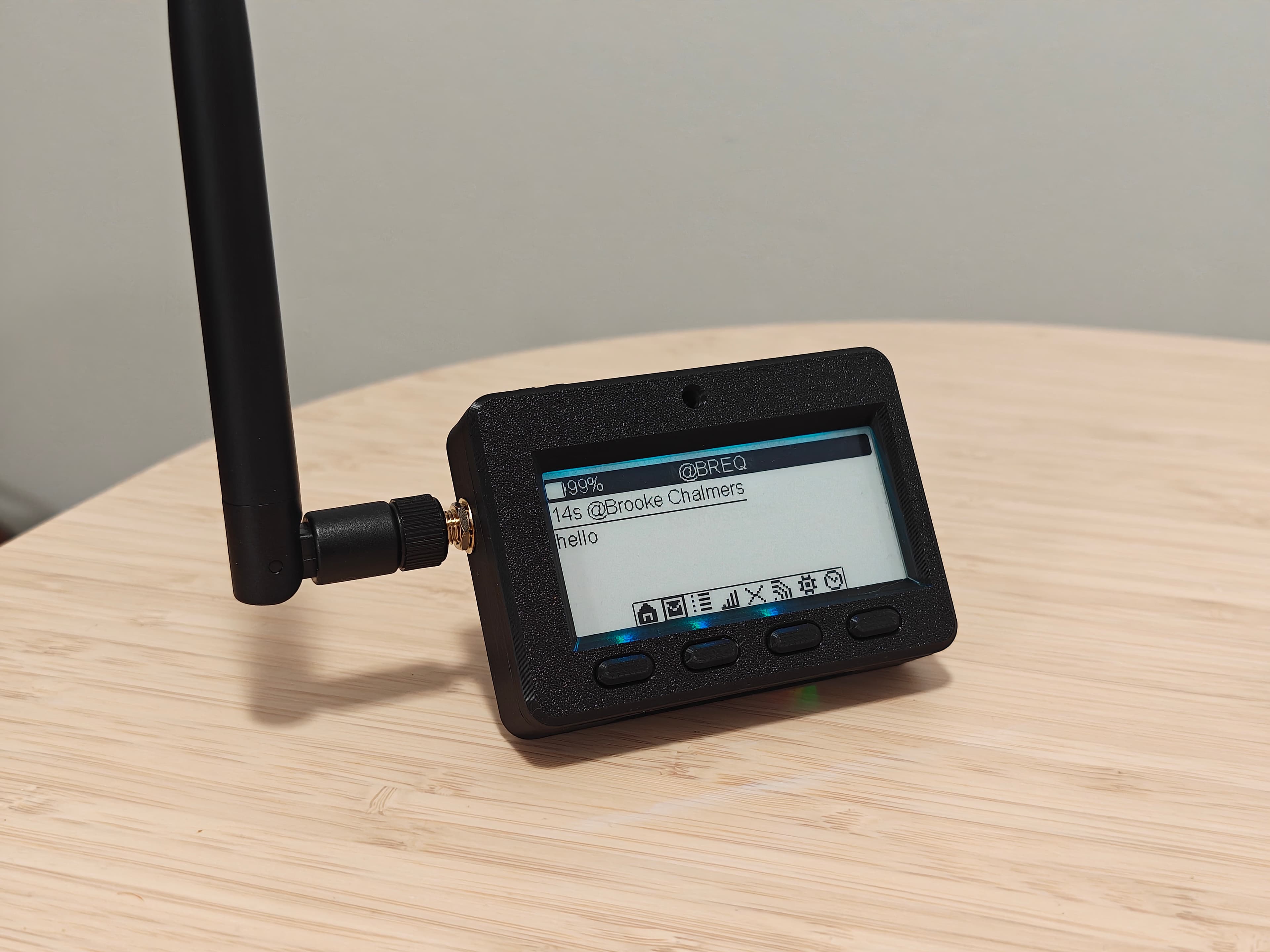
I went with a 2 dBi foldable antenna from Seeed Studio, which meant I only needed to include an SMA port on the outside of the enclosure.
I've been learning Onshape recently, and this was a great project for it -- modifying existing designs is something SketchUp really struggles at. With Onshape, I was able to load in the STEP file, make a sketch off of the wall where I wanted the antenna hole, and extrude the hole in the position I wanted it. I also added more material on the outside/bottom to better support the washer, and cut out part of the inside case to ensure clearance for the end of the SMA connector.


The link to view the design is here!
As it turned out, I had plenty of room to fit the SMA connector while routing the internal coax cable nicely above the stand cutout!


Link to this section Wiring
For a LoRa module, I chose the Wio-SX1262 from Seeed Studio. The SX1262 seems like the most popular choice nowadays for a LoRa chip, and the Wio module has all of the bells and whistles like a TX/RX switch for the antenna and a temperature-compensated crystal oscillator.
In terms of actually connecting it to the ESP32, my first order of business was figuring out what GPIO pins I could steal.
The SX1262 uses SPI for most communication, which is great since it can be chained on the same SPI pins used for the E-Ink panel and the ESP32 module's internal PSRAM. That said, there are a few extra signals I needed to find spare pins for.
- GPIO2: This is the only GPIO unused on the MagTag. However, it has to be held low during boot, and has a pull-down resistor on it. This precludes its use as an input, but it can still be used as an output! I mapped this to NSS (SPI chip select) on the SX1262.
- GPIO18: This is one of the two DAC pins on the ESP32, and the MagTag breaks it out to a 3-pin JST connector at the bottom labeled "A1" for users to connect their own hardware. Since this pin can be used as an input, I wired it to DIO1 (an interrupt signal) from the SX1262.
- GPIO10: This is just a plain digital pin, and the MagTag breaks it out to a 3-pin JST connector labeled "D10." Again, assuming nothing is connected to that port, we can use this as an input, so I wired it to BUSY on the SX1262 (which indicates when the module cannot receive SPI commands).
- GPIO13: This pin is connected to an LED on the back of the MagTag intended for debugging (it's not visible on the front). I wired it to NRST (reset) on the SX1262.
This repurposing gives us enough pins to wire up the radio module, while keeping almost all of the MagTag functionality intact and avoiding the need to make any destructive changes to the PCB.
Note that the SX1262 actually has three "DIO" pins! The Wio module connects DIO2 to the RF switch internally (meaning we don't need to wire to its RF_SW pin), and DIO3 is used for the temperature compensated oscillator.

When I bought the module, I saw that it had castellated edges that I figured would be convenient to solder to. I did not realize they were only a 1 mm pitch! After unsuccessfully attempting to wire to them with the 22 AWG hookup wire I had lying around, I bought some 30 AWG wire that made the process much easier.

To test my pin assignments and make sure I didn't miss anything about the ESP32's GPIO capabilities, I connected the Wio to the GPIOs with lots of slack at first so I could easily reassign pins if needed. Everything seemed to work on the first try!
For those following along at home, here's the final wiring table:
| Wio pin | ESP32 pin name | ESP32 pin |
|---|---|---|
| VCC | 3V3 | 2 |
| GND | GND | 1 |
| NSS | IO2 | 5 |
| NRST | IO13 | 16 |
| SCK | IO36 | 30 |
| MOSI | IO35 | 29 |
| MISO | IO37 | 31 |
| BUSY | IO10 | 13 |
| DIO1 | IO18 | 21 |
To permanently mount the Wio module, I decided to attach it to the top of the ESP32's RF shield. While I would've preferred a more solid mount, neither the MagTag nor the Wio really had any rigid features to mount to.
After shortening and re-soldering the wires, I put some electrical tape on the RF shield so that it wouldn't cause any shorts, then used some E6000 adhesive to attach the Wio module. It's certainly not the most elegant approach, but it seemed like the best I could do with the tools that I had. I clamped everything in a Panavise for a few hours to let everything set.


With the Wio module all the way to one side on the RF shield (centering it would cause it to collide with the stand), everything fit nicely and I was able to close up the enclosure!
Link to this section Firmware
Adding support for a new board to Meshtastic means creating a "variant.h" file which defines macros for pin mappings, hardware types, and configuration parameters.
As it turns out, most of the features on the MagTag were already supported by the Meshtastic firmware, so it was just a matter of adding the right #define statements for the specific pin mappings of the MagTag board.

The obvious place to start was the LoRa radio. Configuring the SX1262 was straightforward using the SPI pin mappings.
The E-Ink display put up slightly more of a fight, but not much! Meshtastic uses the GxEPD2 library for controlling E-Ink displays. While it's intended for use with Waveshare brand display boards, I found through some googling that the SSD1680 chip display used in the MagTag corresponds to the "GxEPD2_290_T94_V2" preset.
The Meshtastic UI looks great on this panel! The firmware makes extensive use partial refresh, a technique where the display contents are updated but the full E-Ink refresh cycle is skipped. This approach typically results in distracting ghosting, but it's not all that noticeable here. The only hiccup I'm experiencing is that display updates are sometimes slow enough to make the UI miss repeated button presses.
Most Meshtastic boards are designed around a single-button interface (press for "next", hold for "select"). The MagTag has four buttons at the front, and its silkscreen indicates that they are intended to be used as directional controls (left/up/down/right). The closest thing that Meshtastic supports comes from the LILYGO T-Deck, which uses a trackball to provide four-directional input. If we configure our four individual buttons using the trackball driver, we get a pretty smooth way to navigate the UI! And while the MagTag doesn't have a "select" button on the front, we can map the BOOT button on the side. (Annoyingly, this button is directly above the RESET button and they look identical -- so don't press the wrong one when you're deep in a menu...)
Like most Adafruit boards with a LiPo battery, the MagTag includes a voltage divider connected to an ADC pin so that user code can read the current battery voltage. Meshtastic directly supports this type of battery reading with a few config options, and can use the battery voltage to produce both a "percent remaining" indicator and to detect if the battery is charging or not.
One of the quirks of Meshtastic is its I2C sensor detection setup: it can scan the node's I2C bus and look for sensors, then broadcast that data to the mesh. This functionality can be used to run a public weather reporting station, or just to make sure a node deployed in a remote location doesn't overheat. This pairs nicely with the STEMMA QT connector exposed on the bottom of the MagTag, which supports connecting and chaining various I2C-based sensors.

The MagTag also includes four sideways-firing NeoPixels which are supposed to illuminate the E-Ink panel. Meshtastic does support NeoPixels through its "ambient lighting" module. Unfortunately, it seems like alignment of the NeoPixels isn't great for this use -- I found it didn't offer an improvement in readability in any lighting conditions I tried.
Link to this section Conclusion

Overall, I'm really pleased with how well this idea came together! I can use my little MagTag node for sending and viewing public messages on the mesh, directly messaging other Meshtastic users in my area, and viewing the list and map of nearby nodes and their signal strength.
While there are definitely some shortcomings like the lack of Bluetooth, this board ended up being a pretty capable Meshtastic node. I'm sure if I spent more time adapting the firmware, I could get a smoother user experience, but it's honestly quite good as it is. I'm excited to continue using this node and I think it's an excellent companion to my fixed node at home.